In modern society, the electrical power system plays a crucial role. Enhancing the safety of grounding devices and the real-time monitoring of these devices is one of the essential measures to ensure the safe operation of transmission lines and the electrical grid. With the rapid development of society, various no-soil environments have emerged, such as concrete floors and high-rise buildings, where grounding bodies are covered by concrete. In these scenarios, traditional "ground rod" methods (installing auxiliary grounding electrodes in the soil) become impractical.
Below, we introduce how to use the ETCR2000 Clamp-On Ground Resistance Tester (hereinafter referred to as the clamp meter) to test the grounding resistance of a single-point grounding body in a no-soil environment. From the perspective of testing principles, the clamp meter can only measure loop resistance and cannot directly measure the resistance of a single-point grounding body. However, by using a test wire and a nearby grounding electrode (such as a well-grounded fire hydrant), we can artificially create a loop for testing. We have summarized two measurement methods: the two-point method and the three-point method.
In this experiment, we plan to use the ETCR2000 Clamp-On Ground Resistance Tester to measure the resistance (RA) of a grounding body (A) in an indoor laboratory. The permissible value for this grounding body's resistance is <4Ω.
1.Two-point method, for which the measurement principle is shown below. This method can measure the approximate value of the grounding body's resistance.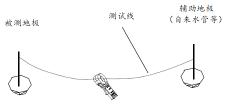
The measured grounding resistance of the grounding body is: R = R_meter - R_aux - R_wire
Note: R_meter is the resistance measured by the clamp meter; R_aux is the grounding resistance of the auxiliary ground electrode; R_wire is the resistance of the test wire.
If the resistance measured by the clamp meter is less than the allowable value for the grounding electrode being tested, then the grounding resistance of the tested electrode meets the standards. If the auxiliary ground electrode is well-grounded (such as a fire hydrant or a metal water pipe), since the grounding resistance of the auxiliary ground electrode is very small, the grounding resistance of the tested ground electrode is approximately equal to the resistance measured by the clamp meter.
Step One: Connect the test wire to point A of the grounding body being tested.
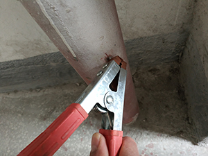
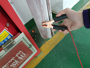
Step Two: Connect the test wire to the fire hydrant at point B, making sure to remove the paint from the surface of the fire hydrant.
Step Three: Measure the resistance between points A and B, which is R = 2.1Ω.
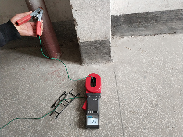
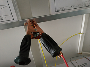
Step Four: Connect the ends of the test wire together and use the clamp meter to measure the resistance of the test wire, RL = 0.4Ω.
Measurement Result: (RA+RB)=R-RL=2.1Ω-0.49Ω=1.61Ω. Since RA < 1.61Ω, which means the grounding resistance at point A meets the standard.
2.Three-point method, for which the measurement principle is shown below. This method can accurately measure the grounding resistance of a grounding body.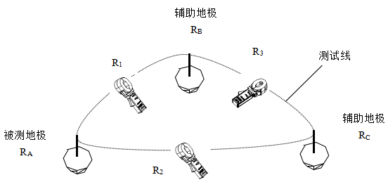
Since: R1 = RA + RB R2 = RA + RC R3 = RB + RC
Therefore: RA = (R1 + R2 - R3) / 2
Note: When measuring R1, there should be no wire connection between AC and BC. The same applies for R2 and R3.
For this method, we need to use a third grounding body at fire hydrant C point, and measure the resistance between AB, AC, and BC, respectively.
Step One: Measure the resistance between AB, R1 = 2.1Ω.
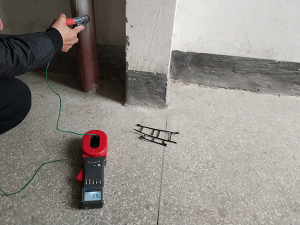
Step Two: Measure the resistance between AC, R2 = 2.9Ω.
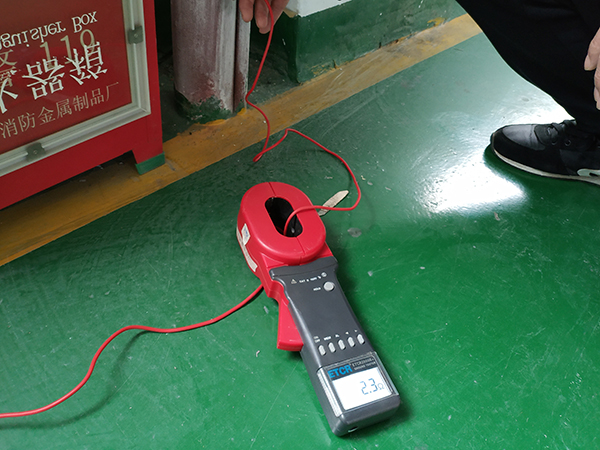
Step Three: Measure the resistance between BC, R3 = 2.3Ω.
Measurement result: RA = (R1 + R2 - R3) / 2 = (2.1 + 2.9 - 2.3) / 2 = 1.35Ω, indicating the grounding resistance at point A is within acceptable limits. For ease of memory, the three grounding bodies can be visualized as forming a triangle, where the resistance of the grounding body under test equals the sum of the resistances on the adjacent sides, minus the resistance on the opposite side, divided by 2.
The test results also demonstrate that the clamp-on ground resistance meter, using both the two-point and three-point methods, can quickly measure the grounding resistance of a single-point grounding body. This method is applicable in situations where traditional ground stake resistance testers cannot be used.

info@etcr.net
(86-757)66860936
(+86)13802922567


 CN
CN